Latest Go Box Case – By Mike Sorensen K9KQX
Since getting my ticket a few years back, I’ve dabbled a little with go box cases. Many of you saw the wood box I created for my IC-7300. That was my actual shack in the house as I used to set up next to end table by the couch. Since then I have a real desk at home and traded the original go box.
Well this past summer I picked up a FT-450D from a SK and decided that I’d try another go box. This time with a shallow depth 4U high Gator box. I wanted it to be reasonable small, but robust to handle in shipment.
One of my design goals with this setup was a self-contained HF setup, with the computer and monitor in the case somehow. Ideally all everything but the antenna would fit in the case.
So, to start with, using an FT-450d has its good and bad points. The good points being a decent ATU, bright display, and good contrasting text on the front panel controls. The bad points are no panadapter, and probably the biggest draw back on space consideration is the lack of a USB interface for digital modes. Because of that I needed to use a Signalink which eats up room in the case.
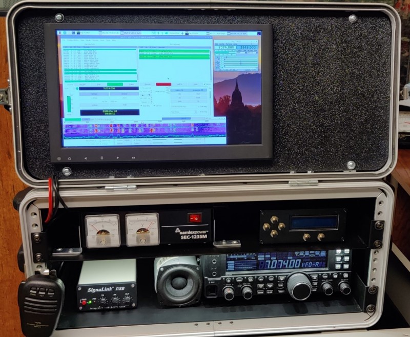
I purchased two metal shelves about 10 inches deep and mounted the 450D and Signalink on the bottom shelf. The top shelf is a power supply and my homebuilt Magnetic loop stepper motor controller. This would allow band changes without having to get up and mess with the loop.
Below if notice I have LED lighting tape strip mounted on the upper shelf to light up the lower section to read the display easier. This will also provide lighting at night to write on paper. I got this from Menards, and these lights when run off DC don’t generate any RFI.
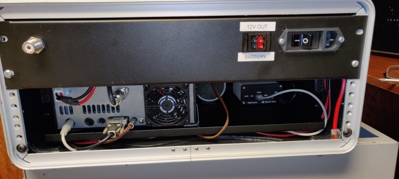
Next, I wanted the ability to run either off batteries or 120v, so I add at Samlex battery backup module(BBM-1225) This neat little device will charge a 12v lead acid battery from the Samlex 12v power supply. If the power supply is off, the battery will take over without any cable changes.
There’re also some Anderson power pole distribution blocks in the back to hook things up neatly, but allow for easy changes if needed. That panel on the back is a 2U server rack blanking panel. I installed the power switch and power poles on the back to hook up the battery and to power an external device easily.
Finally, I had a strong desire to integrate a computer in the unit somehow.
Reason were the following:
- I did not want to take my laptop outside.
- Desired to have a GPS receiver for a time source from satellites, thus no internet needed for accurate FT8 time source. Accurate time is needed for FT8, and helpful for loggin
- Wanted something low power that would run directly off of 12v, thus making it easy to run off a car battery
- Wanted computer integrated to keep the rats nest of wires to a minimum or well hidden.
- Self-contained go box that is 100% ready, just grab and go, and don’t forget the antenna
I purchased the following for the computer setup
- 12” 1920×1080 HDMI monitor from ebay(TOGUARD 12” HDMI HD display)
- Raspberry Pi4 Model B 4GB ram Adafruit PID 4269
- Zero2Go Omini Multi Channel Power supply Adafruit PID 4114
- Adafruit Ultimate GPS breakout ver 3 Adafruit PID 746
- Aluminum Metal Heatsink Raspberry pi 4 Case Adafruit PID 4341
- Qty 1 Stacking Header extra long Adafruit PID 1979
- Qty 1 Stacking Header standard Adafruit PID 4079
- 12”x24” 1/8” textured plastic sheet Parts-express Part 265-948
- 16gb MicroSD card, from anywhere
- Micro HDMI to HDMI cable less then 3 foot long is good enough(I got mine off of Amazon)
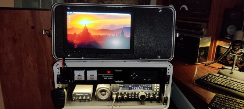
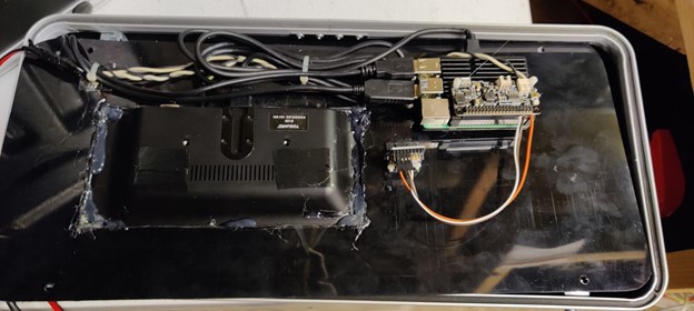
I chose to hinge the front cover, and use the textured plastic as a bezal to mount the monitor, Pi and GPS receiver. You can cut that plastic with a jigsaw or band saw, and then a sander to round the corners. The cutout for the monitor I did with a Dremel. Monitor mounted from the front, and yes if you look at that sloppy job its hot glue around the monitor. I couldn’t come up with any fancy way to attach it.
Basic High level procedures for setting up the Pi with the GPS receiver
- Download the latest raspberry pi OS image from raspberrypi.org
- Follow instructions to image a microSD card and install it in the computer
- Connect the monitor and Pi and keyboard temporarily on a desk to get working
- Learn how to run updates on OS from above raspberrypi.org tutorials online
- Install Zero2Go DC power supply, this converts 12v down to 5 volts, read notes below on this further down
- Install GPS receiver and take a look at some general instructions on setting up the Pi as a NTP time server here below. Just read the instructions after the initial raspberry pi image part https://github.com/TinajaLabs/ansible-role-ntp-gps/blob/master/README.md There are other examples out there, and this is where I’ll leave it open for others to research as there might be better ways.
Zero2Go board install notes.
This board in theory should be easy to setup, but using a Pi4 creates some headaches due to new OS versions of software. Go to there website for details, but even then you may run into issues. There are configuration step to install there software so that you can configure the board to boot the pi up when power is applied, or to remain off and requiring you to push a button on the right side of the board. Since I don’t have access to the button, I needed to install there software to change the setting.
Unfortunately, after installing the software, and making the change to boot up at power on, caused some issues after the first reboot. The zero2go board would constantly reboot the pi after login if I was connected only by 12v. If I use the pi USB power supply, it wouldn’t do that. I tried everything and decided to just remove there software so it wouldn’t start up at boot. This stopped the reboot, and the card remembers my changes, so next time it will continue to boot up when power is applied.
So basically, install the software, change the settings to the zero2go card to have it boot when power is applied, and uninstall the software.
Conclusion
Overall, I was impressed at the performance of the Pi 4 in this use case. FT8 is CPU intensive and generally doesn’t decode fast enough on a Pi3. On a Pi 4 its usable. I found that it would decode a good 8 to 10 signal quickly and then another 5 to 6 a bit past the starting time for the next transmission. That’s not ideal since the timing would be off when you responded to a QSO. But the stronger, easily decoded signals popped up fast and it was able to transmit on time.
Using FLRig control was fairly easy to setup. I was using a usb to serial cable for the FT450D, and had to determine what comm port to use in Linux
Setting up the Signalink was a bit more of headache. Mostly the pain was self induced. The internal jumpers on my signalink are loose from changing it up on many rigs over the years. I fought that for a while until I finally just used a new dip socket to fix the problem. After that, it worked just fine.
Future plans, I’d like to shoehorn a 2m/440 rig in there but that signalink and speaker is in the way. I might relocate the speaker to the right of the monitor, and I may permanently modify the signal link up near the monitor too. I just have to extend the 3 volume controls to the front with some wire. Sort of a remote head Signalink.
Key ham radio apps installed
- FLrig – Rig control
- FLDigi – PSK31 and related digital/CW modes
- WSJT-x FT8/JT65 and related
- CQRLog Logging program
- PiGate, a Winlink version for Linux for email over HF
- And a variety of other apps to long to mention here.
Below is WSJT-X with FLDigi running on the right. Yes this is a small screen, your gonna need reading glasses, but it works ?